
Update February 27, 2022:
I have updated the links below to be more useful. In some cases I have linked to archived versions of websites if those websites are no longer available. I have also posted a copy of Randy’s instruction manual here.
Update June 19, 2019:
Today I heard about the TC4+ Coffee Roaster Shield - TC4 PLUS. While it isn’t made specifically for the HotTop, it might be a solution for those looking for remote control of an older HotTop model.
Update February 4, 2019
The MLGB-LLC website for the HTRI boards hasn’t worked for some time now and I presume the boards are no longer in production. Several people have asked me where else to find the boards and unfortunately, I have no good leads to provide.
Also, HotTop has discontinued the 8828B model and is also no longer selling the 8828B control panels to upgrade older 8828P models. More info from HotTop:
https://www.hottopamericas.com/upgrade.html
Overview
The latest roaster hack I have undertaken is the installation of an HTRI control board from MLGP Properties (via webarchive). The HTRI consists of an HTC shield* attached to an TC4 board. The HTC is the control board that logically interfaces between the HotTop and the laptop and the TC4 interfaces between the thermocouples (replacing my data-logger) and the laptop. When stacked, the two boards allow one to control the roaster and simultaneously read up to four thermocouples. Using roast-profiling software and the HTRI, one gains the ability to not only control the roaster in a fly-by-wire fashion, but also create conditional automation of the roaster. More on that in later posts.
See also: HotTop Resources
I relied heavily on Randy Glass’s instructions (original archived here from a version created September 10, 2012 and obtained by me on March 12, 2016) for installing the board. I also pulled from experience installing thermocouples in the same roaster five years ago.
The boards I received are different from what Randy has documented but the installation process is basically the same. The major differences are:
- The boards I have do not require a jumper-wire between them. All interconnections are made via headers.
- There is no dedicated ground wire for the boards. Ground and power are provided to the boards via the USB cable connection and/or the multi-wire connector from the HotTop main board.
The process, in a nutshell is:
- Disassembly and cleaning
- Determining thermocouple placement
- Thermocouple Placement
- Configuring Artisan
- HTRI Mounting
- HotTop Configuration
Disassembly
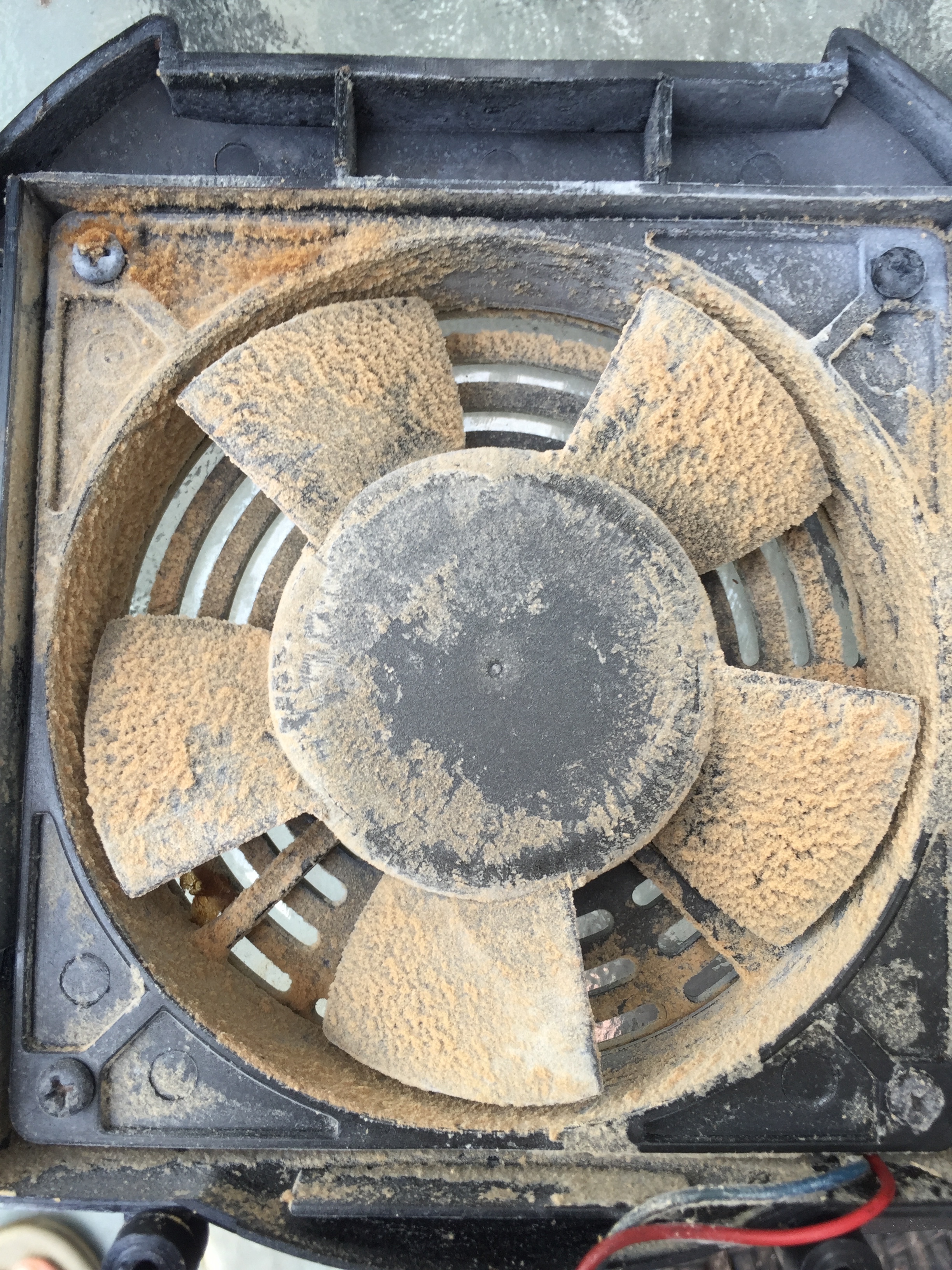
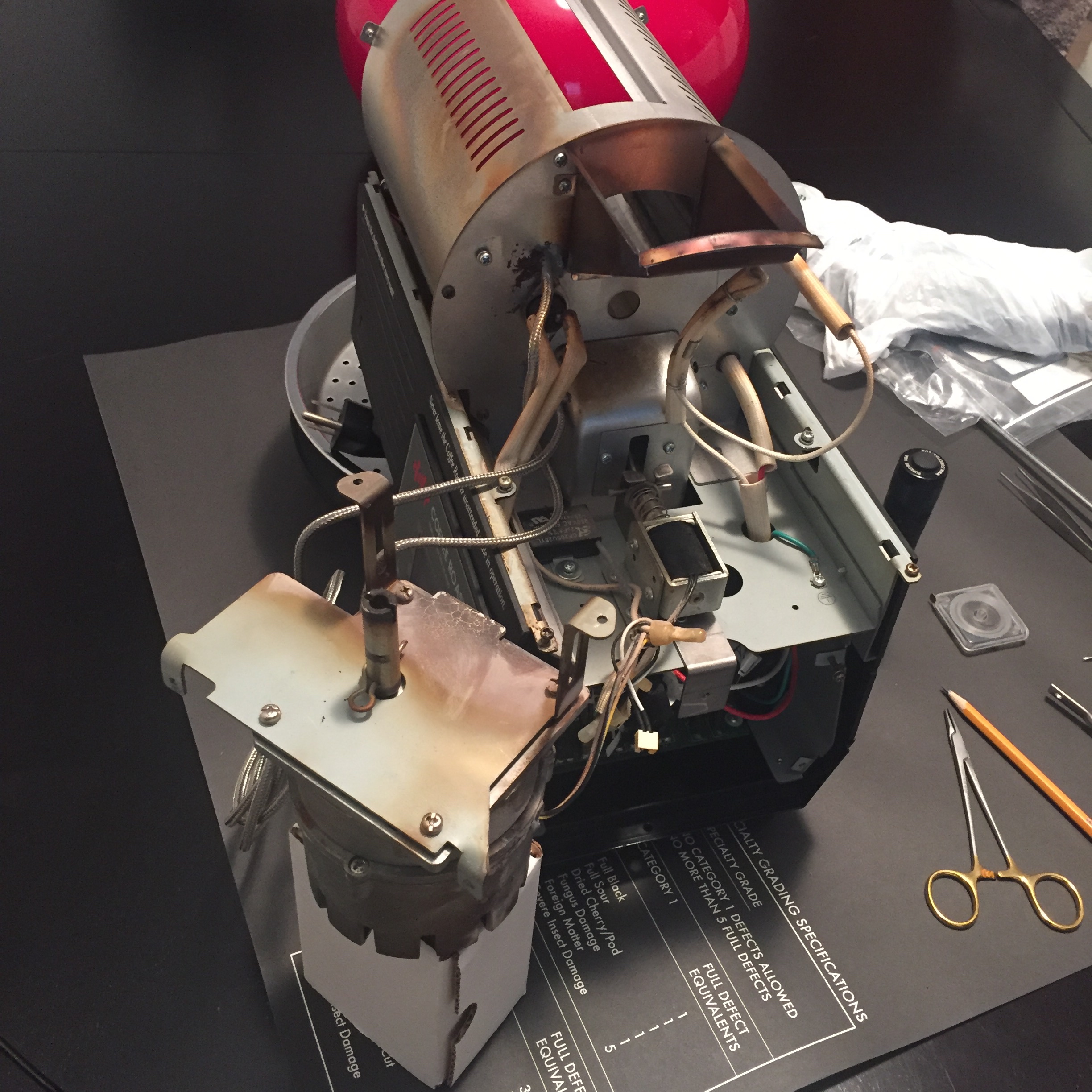
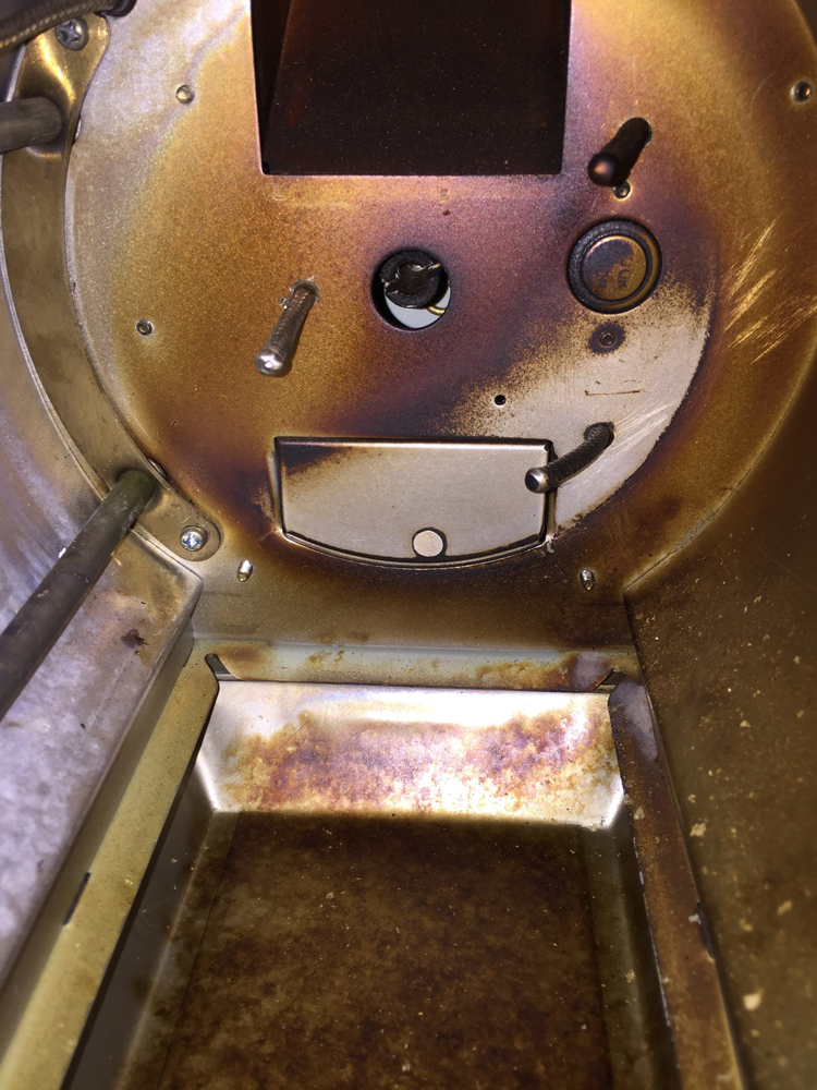
The first step is disassembly and cleaning. This is a rare opportunity to do a deep-clean of the roaster and mine needed it. There was creosote-buildup on several surfaces, including the drum motor that I was able to easily remove. I used a clean paint brush, hand-vac, and compressed air to clean the machine.
Tip: As I remove screws, I try to put them back in the original hole for safe-keeping. That helps prevent me from losing them and also I know what screws go where.
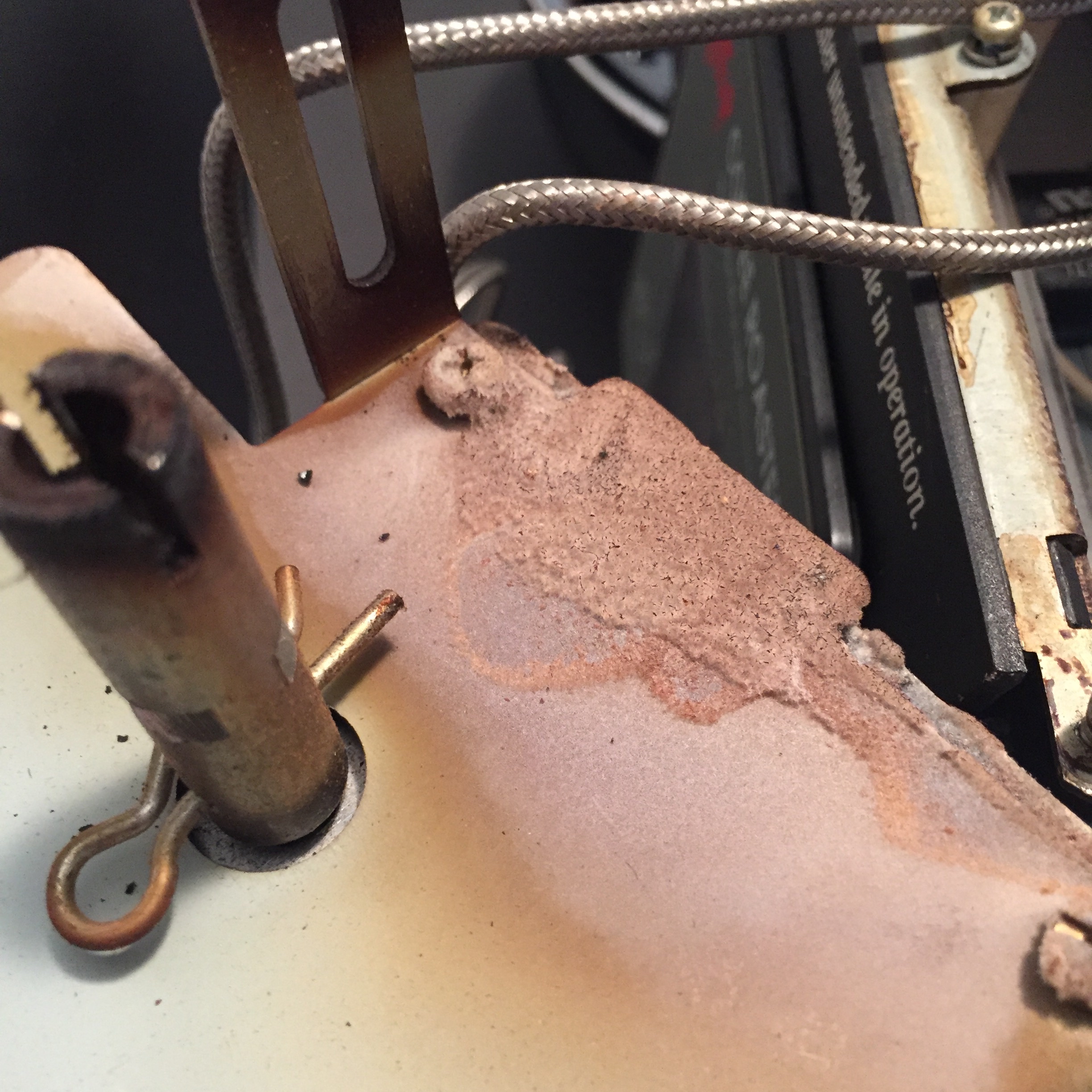
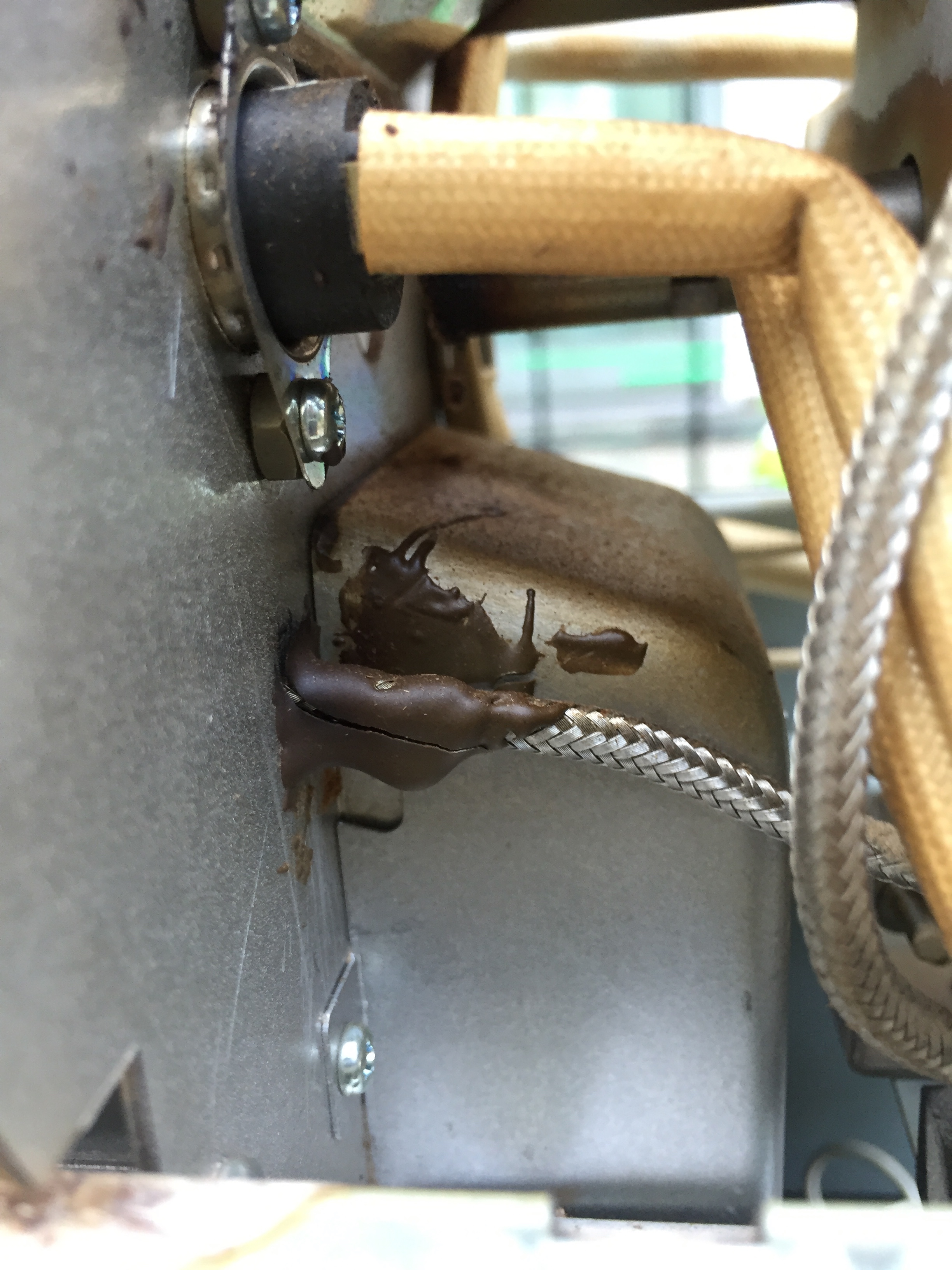
During disassembly and cleaning I also inspected everything and found that one of the original epoxy-welds from the probe installation back in 2011 had cracked. After the roaster was all cleaned and mostly disassembled I applied more epoxy to secure the thermocouple before doing any more work.
It’s worth noting that this particular probe is the bean mass temp (BT) probe and is in constant-contact with the moving bean mass. The stress of that contact is likely a big part of the reason that weld cracked. Something to note if you are installing a BT probe; you may consider using a compression fitting at the back plate to support the probe. In my installation, the epoxy-weld supports the probe.
Determining Thermocouple-placement
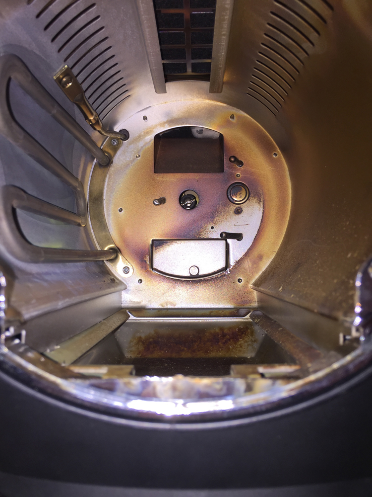
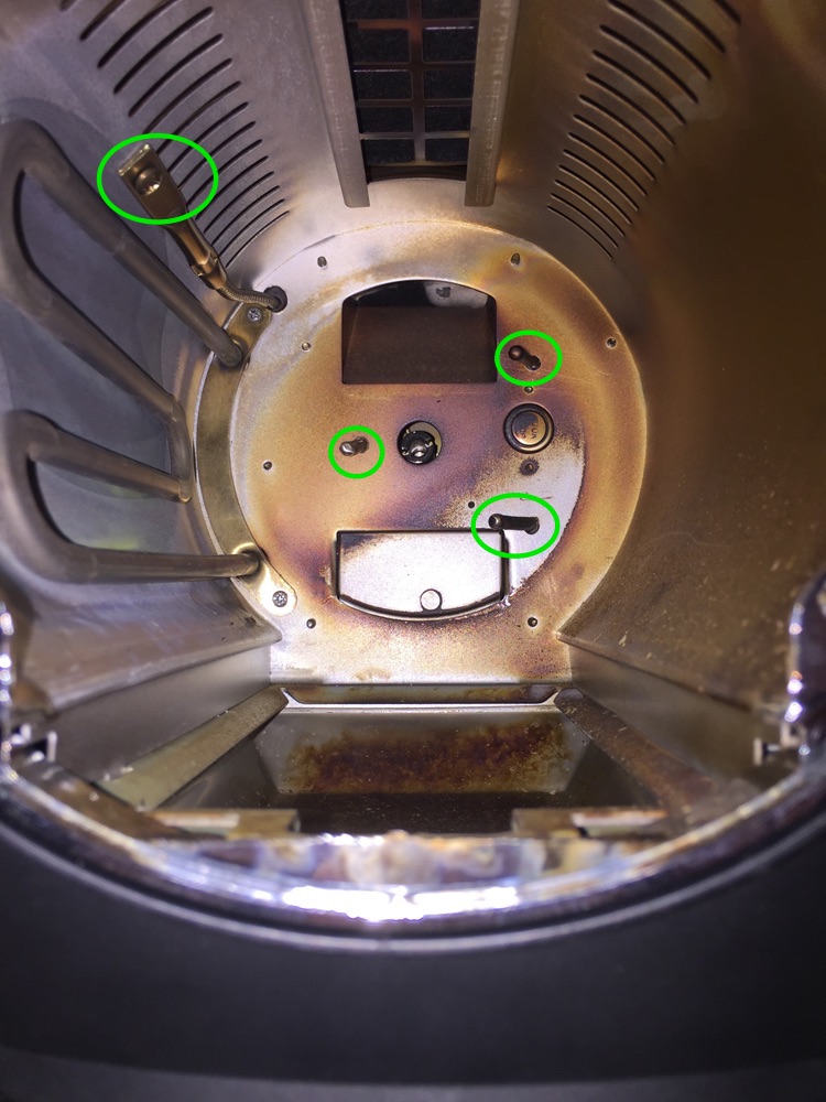
I previously installed two thermocouples (TC); one to read the bean mass temp (BT) and one for the environment temp (ET) and they work great. However, with the TC4 board I can read up to four TCs simultaneously and as a good friend of mine says; anything worth doing is worth overdoing. For the new board I placed the third probe just above the heating element and the fourth probe inside the drum to get a second ET reading.
One feature of the roast-logging software I use, Artisan Roaster Scope is that I can create a virtual probe by combining two or more and averaging the results. That could be interesting. More to come on that.
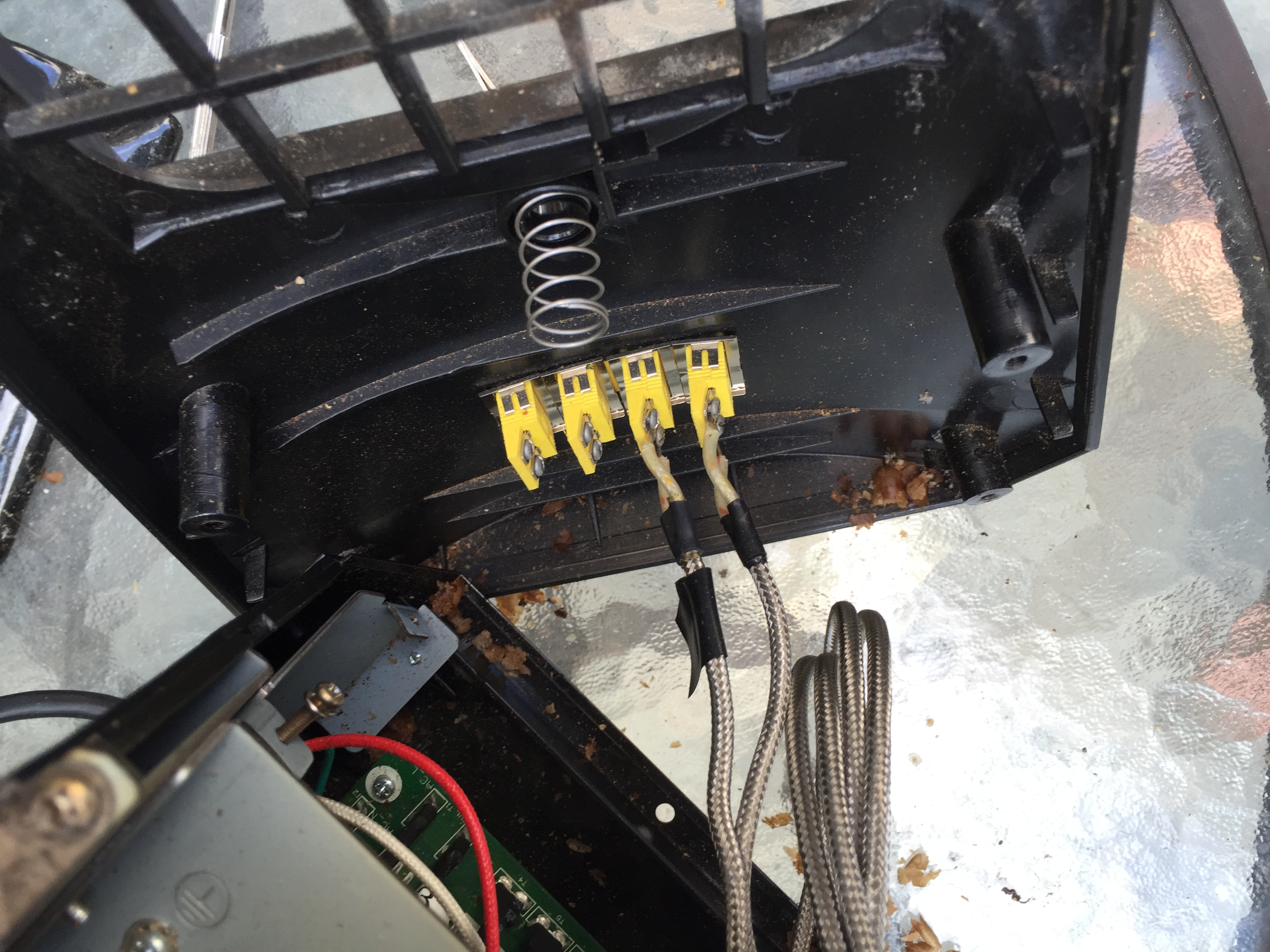
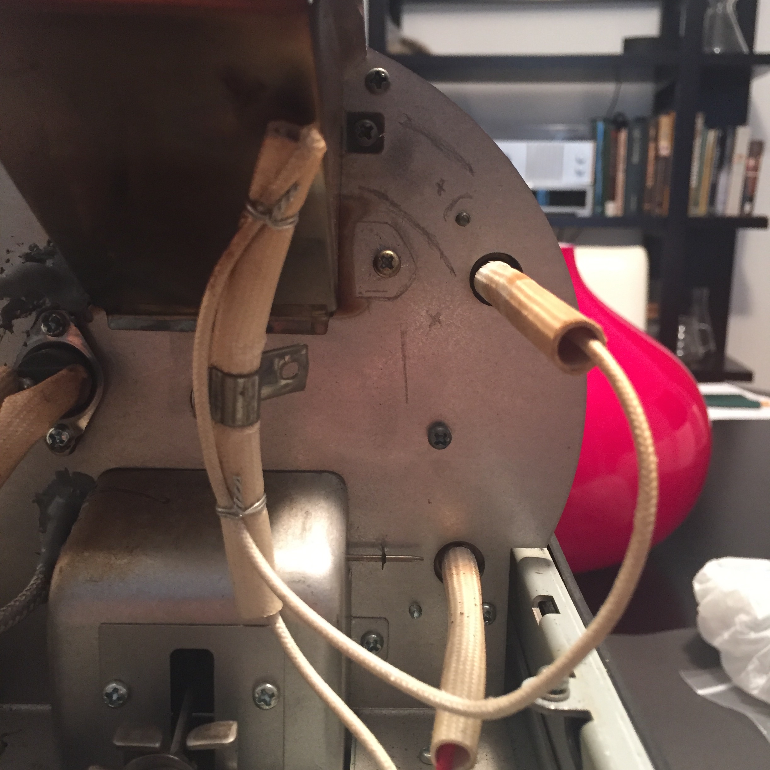
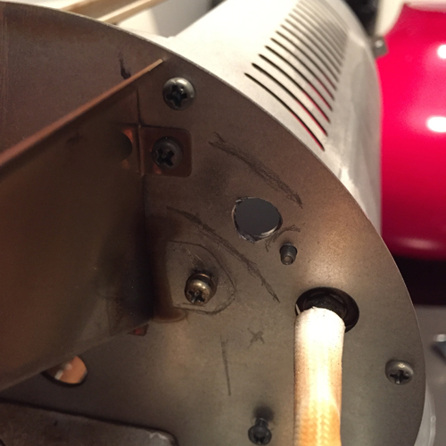
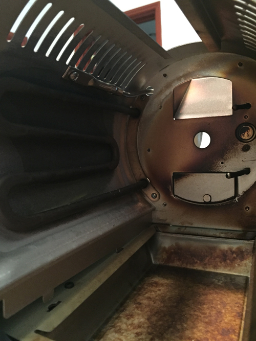
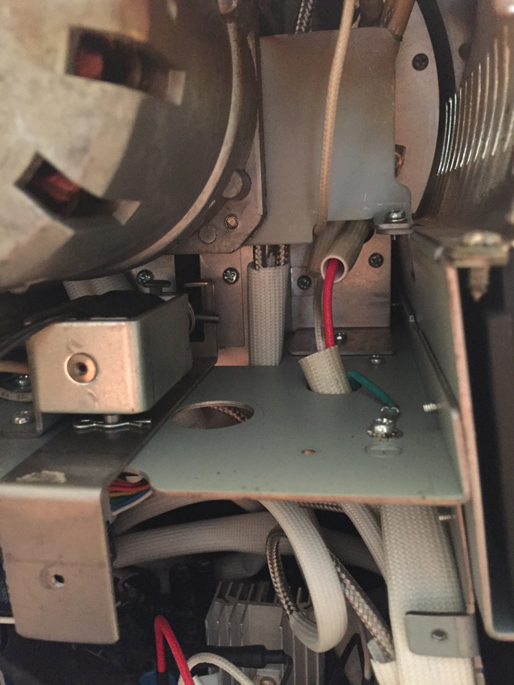
In the images below, you can see my markings indicating where the shroud is and where the drum is on the other side of the back plate. I’ve temporarily removed the motor and the heating-element wire-bracket and measured and marked where obstacles are on the other side of the back-plate.
Element Thermocouple Placement
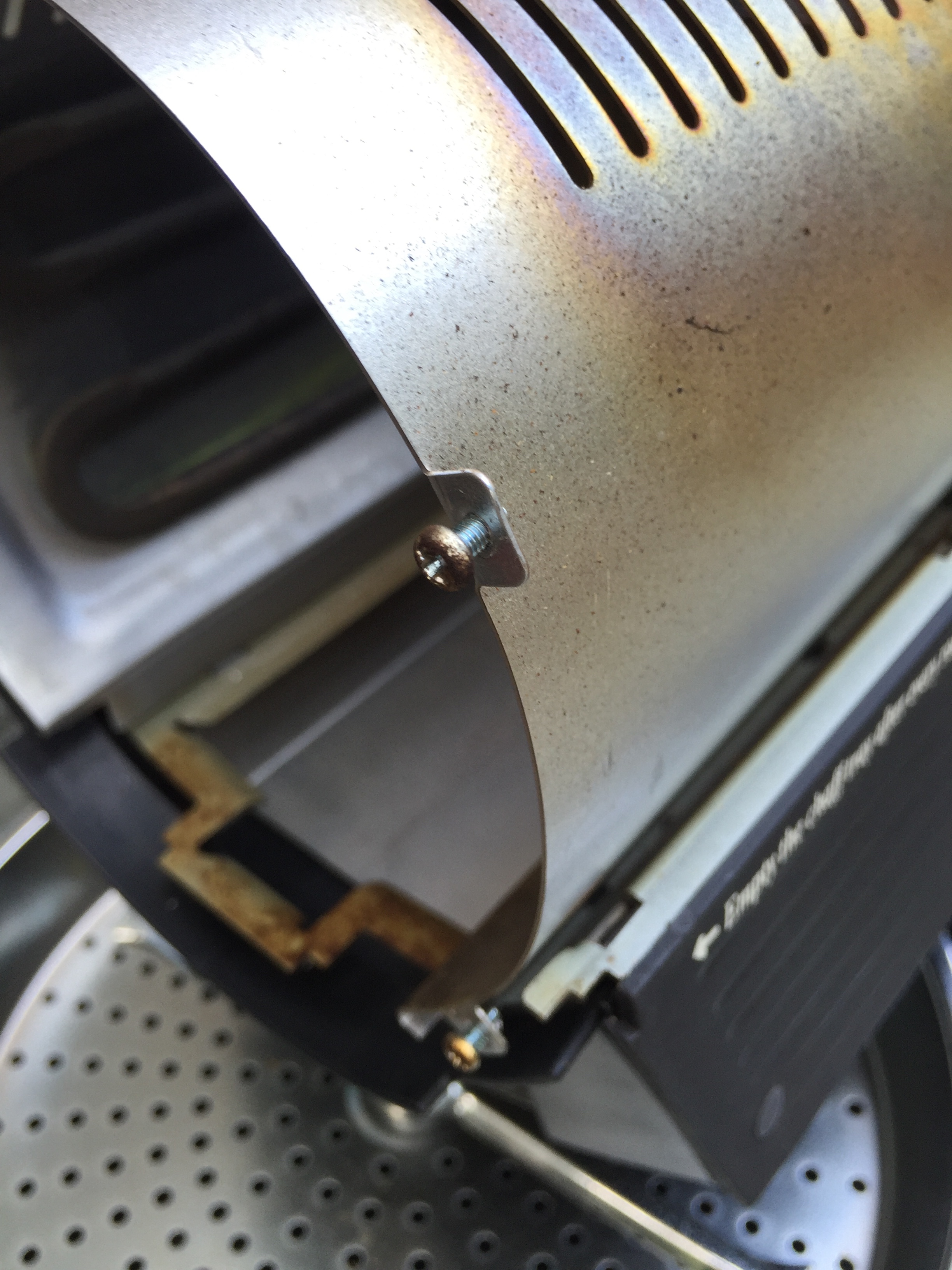
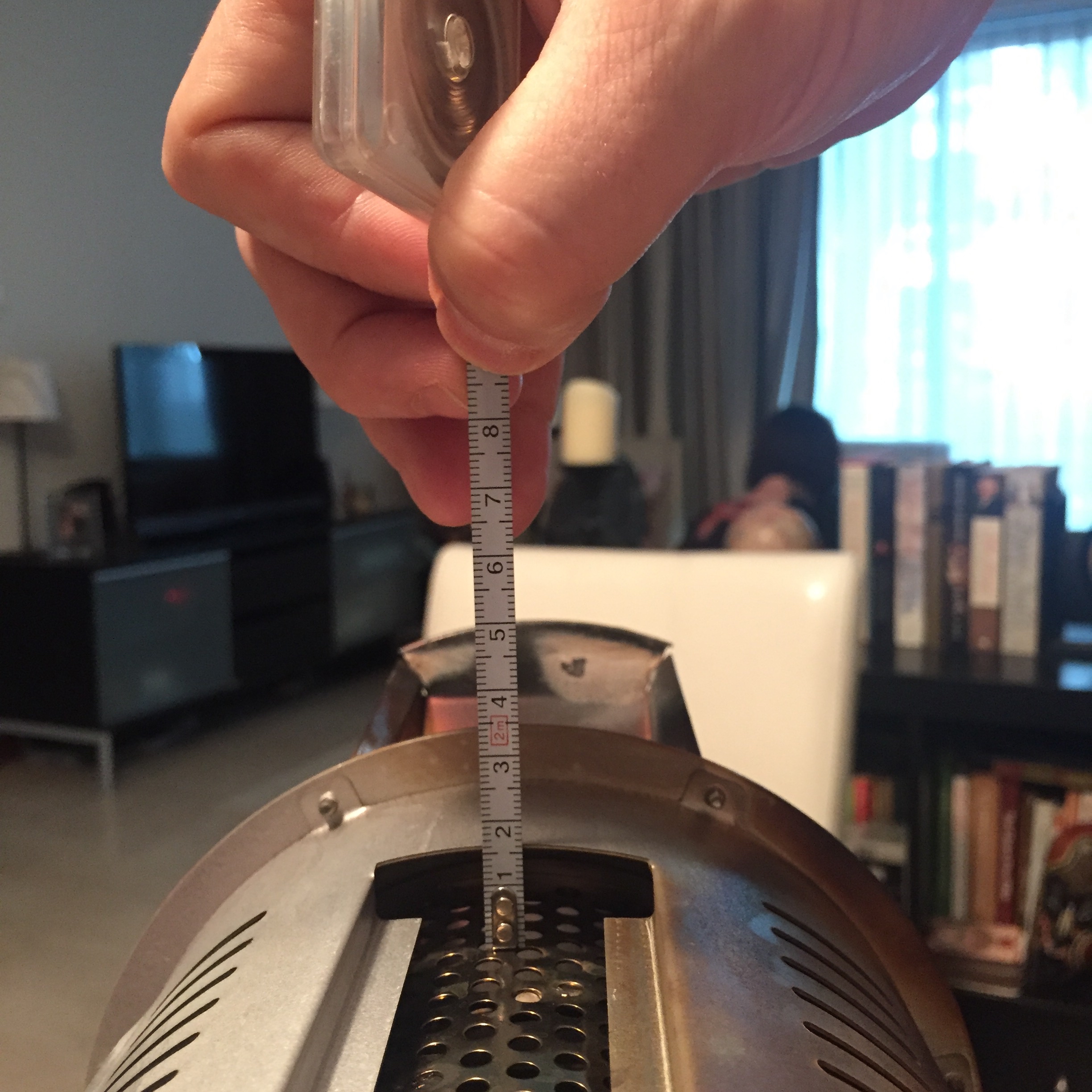
One of the two additional thermocouples I am placing will be to measure something close to maximum temperature (not to be confused with Staub’s concept of maximum environment temperature or MET). I assume the point of highest temperature is near the heating element so I placed the element probe directly above it, being careful not to obstruct the ventilation slots.
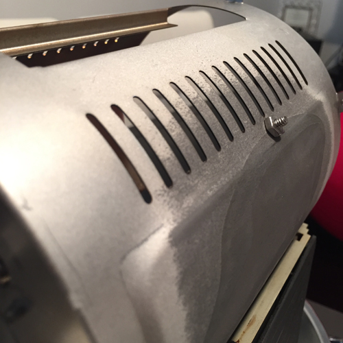
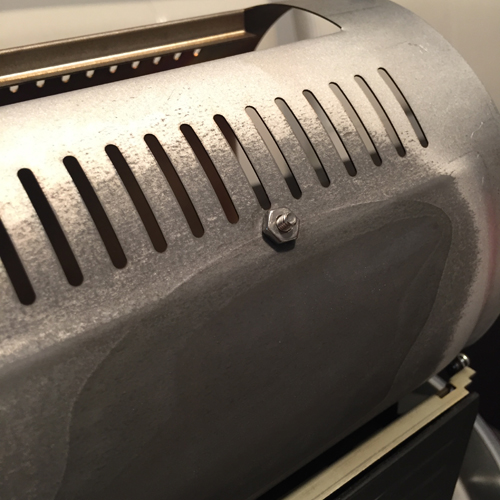
In the last image above, you can see three distinct levels of discoloration on the shroud, created by heat from the heating element. I think the hottest point in the roaster is in the darkest section. However, I chose to mount above the element to avoid the mounting bracket of the element and even there, I was close enough to the bracket that the drill shaved a bit of it to make the hole…whoops.
Configuring Artisan v. 0.9.8
To configure Artisan version 0.9.8(1) to read the HTRI, perform the following:
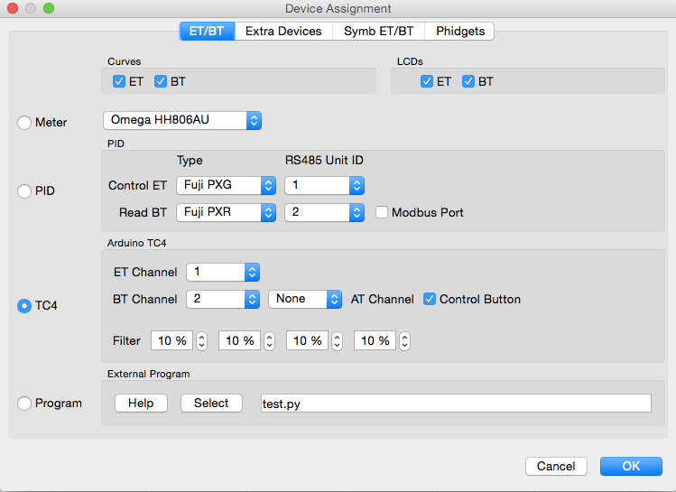
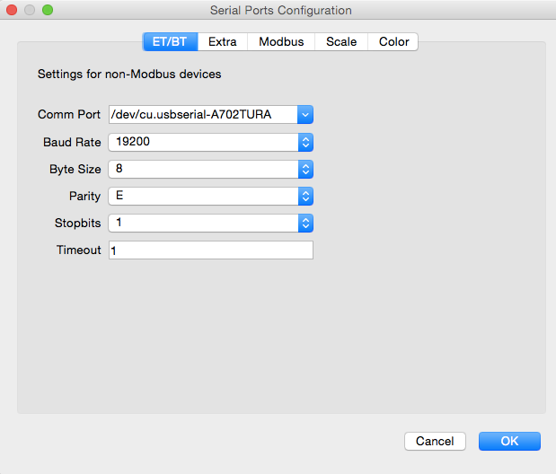
Under Config → Device… select “TC4” as the device and click the “OK” button. In the next window that pops-up, select the comm port you will be using (in my case it’s the USB port).
These settings will provide access to the HTRI boards and TC1 and TC2. If you have only installed two thermocouples, you should now have access to read the HTRI and can now configure your sliders.
Configuring Extra TCs
For installations of three or more thermocouples, perform the following:
Again in the Devices menu, select the “Extra Devices” tab. Click the “Add” button and in the “Device” drop-down menu, select “TC4_34.” This will provide access to TC numbers 3 and 4 and will allow you to name them and assign a color to their curve lines.
Configuring Sliders
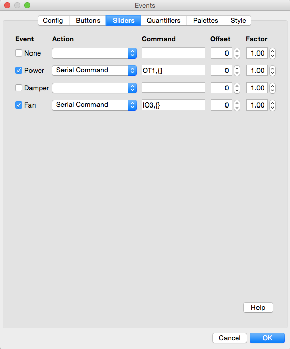
To control the fan and heating element of the roaster via Artisan, you can add sliders to Artisan via Config → Events… and selecting the “Sliders” tab.
Check to enable the Power and Fan sliders and select “Serial Command” from the Action drop-down menus for both. The serial command for the Power slider is OT1,{} and for the Fan slider it’s IO3,{} (see picture below).
Note: There is other documentation recommending using the command DCFAN instead of IO3. Both will control the fan. IO3 issues the command to the fan immediately. DCFAN “Limits the increase in duty to 25 points per second to address fan inrush current on Hottop (and possibly other) roasters.” The “inrush current” problem manifested in limited cases right after pressing EJECT with the fan set to 0% before-hand. More details here: http://www.mlgp-llc.com/htri/fan_notice.html (via webarchive).
Note; in the “Action” drop-down menu, there are options labeled “HotTop.” These are for the HotTop model KN-8828B-2-K+, which has the HTRI functionality built-in. If you have the 2-K+ model, you don’t need to install the HTRI at all.
These sliders give you control of both the fan and power in 1% increments. If you want to run your element at 33%, you can now use the slider to do that, whereas before you only had 25% increments for the fan and 10% increments for the heater!
Tip: Now is also a good time to connect everything logically and test functionality before you proceed to mounting the boards and stuffing cables into every free nook-and-cranny. In this way you can be sure everything functions properly before installation, after-which it becomes more difficult to troubleshoot physical connections vs software problems, etc.
HTRI Mounting
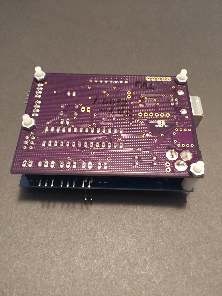
I replaced the stock nylon posts that secured the board and shield together, with long nylon screws so that I could attach the board to the side of the roaster easily. This is a relatively quick and painless way to mount the boards in the roaster and provides relatively easy-access to attach cables.
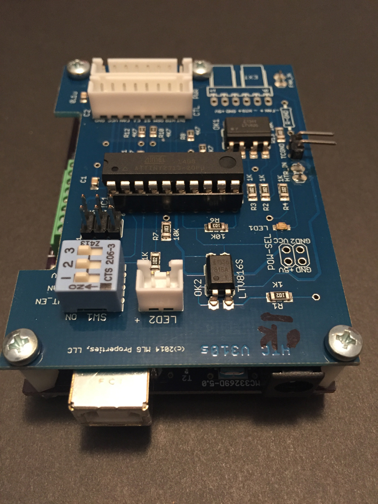
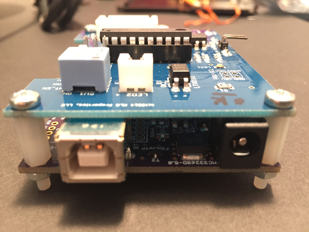
Below are some pictures of the boards as I received them. Previous versions of the HTRI had a jumper-cable to connect the two boards. Now the only cable included is for an optional LED light (to indicate “heater on”), which I chose not to install*.
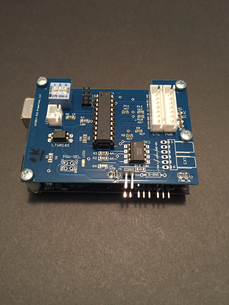
The HTRI sits inline between the HotTop control panel and main board using an extra 8-wire cable (for the 8828-B model, other models may have a different cable). Connect the control panel to the jack marked CTL on the HTC and connect the main board to the jack marked PWR.
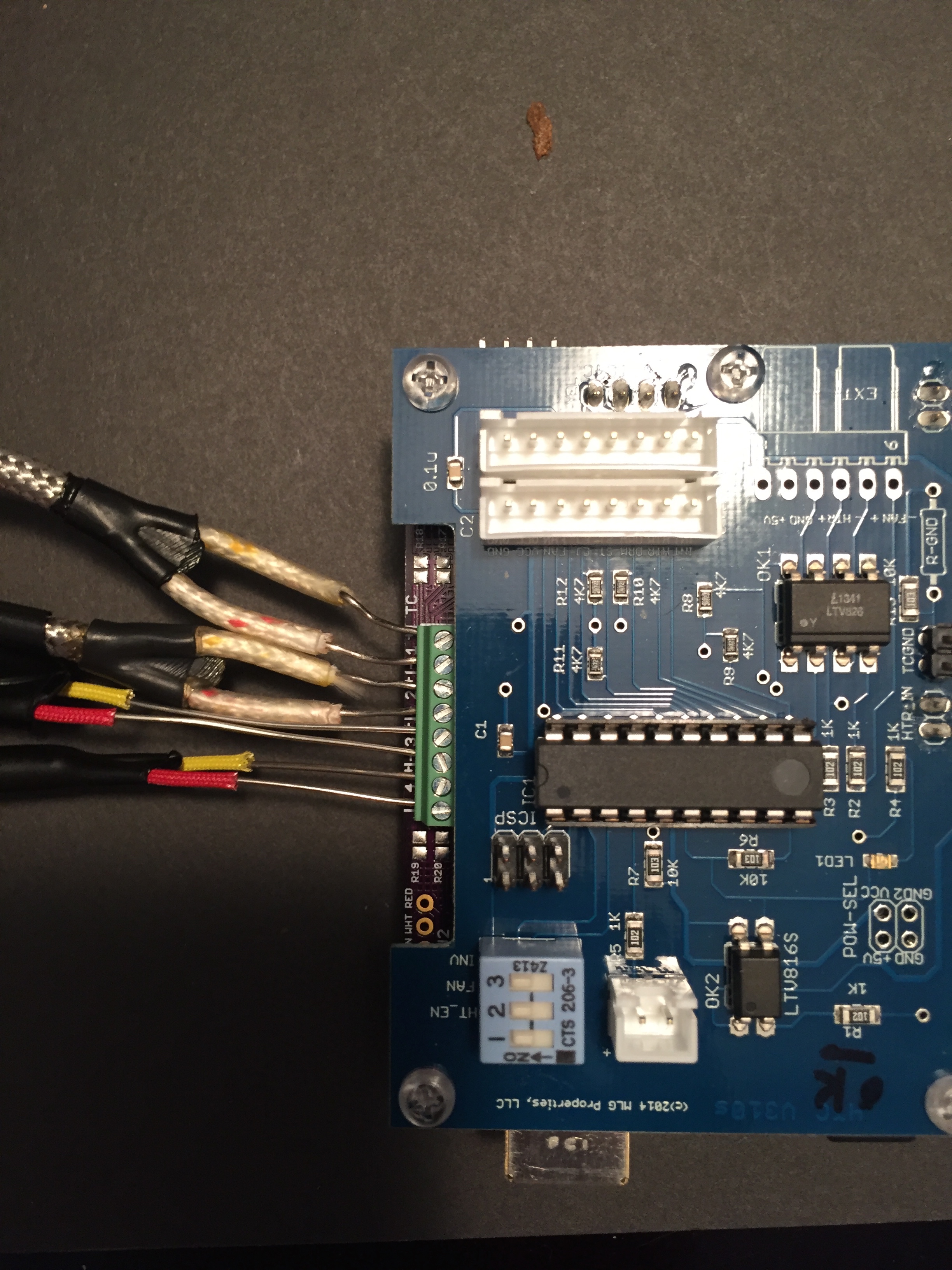
The sockets for the thermocouples are labeled 1 - 4, + and -. Standard color-coding for the thermocouple wires is red markings for negative, yellow markings for positive. The number-label for the TCs on the board matches labels used by Artisan to identify the probes: TC1 through TC4. With my previous install of TCs, I used TC1 for ET and TC2 for BT so I continued that convention with the HTC boards and made the element probe TC3 and the second ET probe TC4.
Note: The TC4 may expect the ET probe to be connected to TC1, to be used as input for the PID controller. Therefore I recommend ensuring the ET probe is connected to TC1, just in case. The reason I suspect the TC4 expects TC1 to be connected to the ET probe is this statement in the list of commands available via the TC4:
     PID,CHAN,i
     ----------
     Sets the input for the PID controller.
     i = a decimal value 1 to 4 representing a physical port (TC1, TC2, TC3, TC4).
     Example:
      CHAN,2100
      PID,CHAN,2
       this results in the sensor connected to physical port TC2 being
       used by the PID. TC2 was mapped to logical channel chan1 which
       corresponds to ET when using Artisan Roasting Scope
The minimum connections necessary to use the HTRI to monitor and control a roast:
- Multi-cable connections to the HotTop control panel and main board
- USB cable between the HTRI and your laptop
- At least one thermocouple
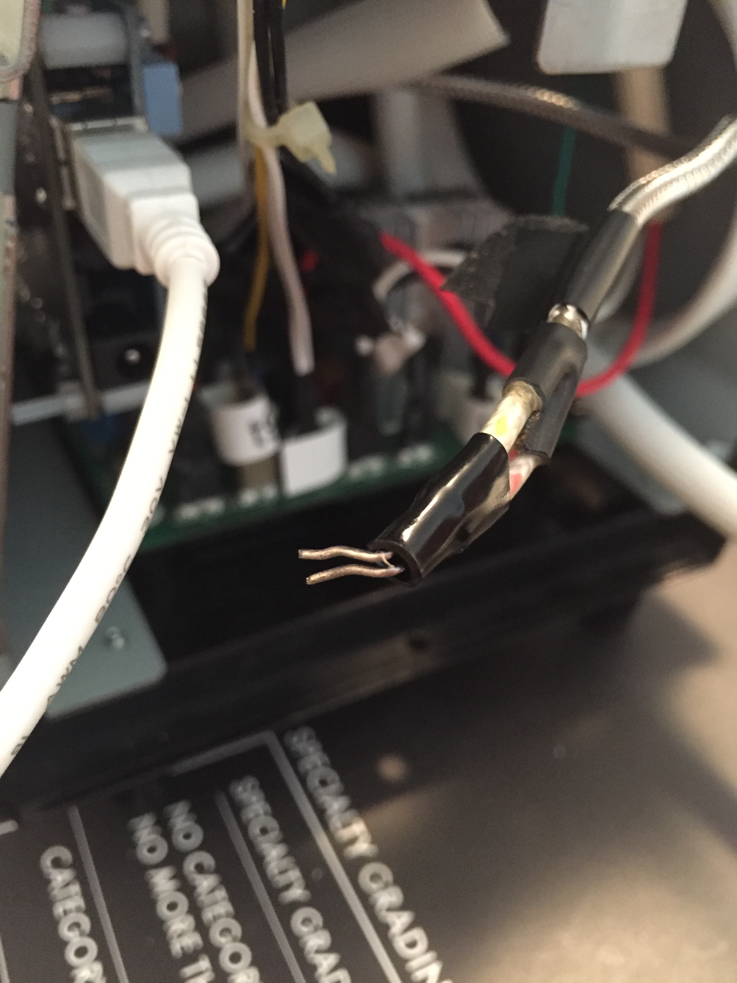
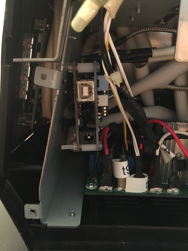
Tip: To prevent the thermocouple leads from contacting each other, I added a short piece of shrink-tubing to the ends of each. In the first picture below, the tubing has not been added. The next two pictures show tubing added to one of the thermocouples. Due to the angle I mounted the boards (perpendicular to the bottom of the roaster) the TC connectors on the board face straight upwards. I brought the TCs in from the side, which meant I needed a 90° bend in the exposed tips in order to insert them into the board connectors.
Tip: You can (and should) verify TC functionality before mounting the board or even stuffing wires into their final place. Once you have all TCs mounted where you want them, connect them to the TC4 board and connect the USB cable to your laptop. This will provide power to the board and allow it to read the TCs. If one TC isn’t working, verify correct +/- connection and verify you don’t have a ground loop created somewhere by the TC shield contacting the metal roaster chassis.
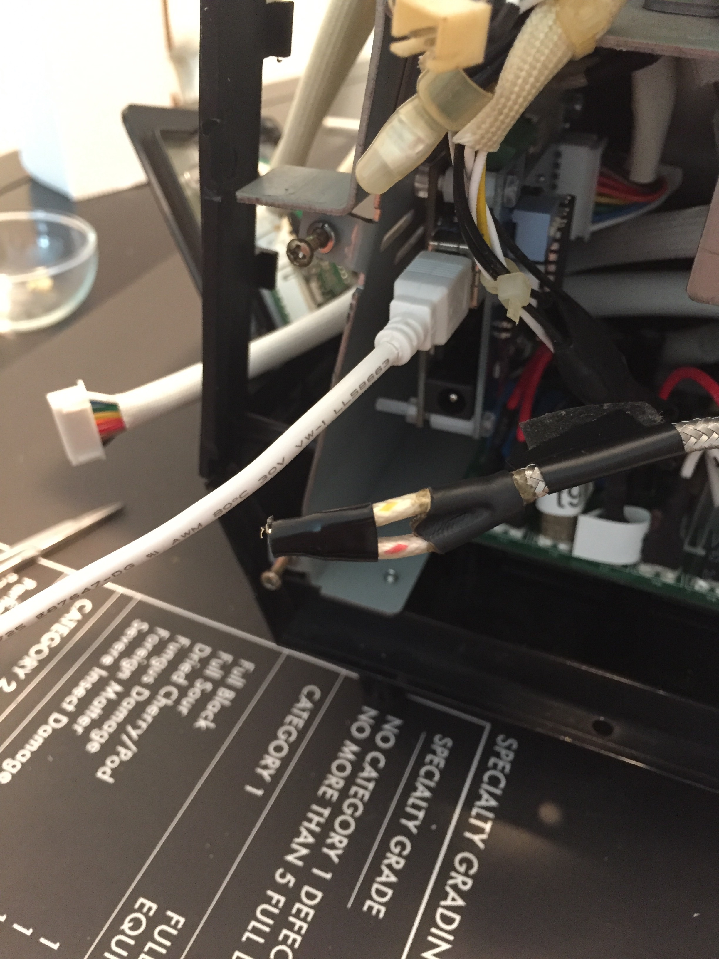
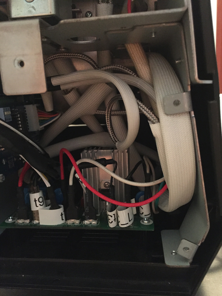
With wiring coiled from four TCs plus insulation for the TCs, plus the HTC + TC boards, space is very limited. My biggest challenge for this install was getting everything to fit well within the roaster. It really helps to have insulation on the TCs so that contact with other components or the roaster chassis does not become an electrical grounding or shorting problem.
HotTop Configuration
Once you have the device installed in the HotTop and functioning properly, the last step is to configure a special profile for your HotTop 8828B. This process is unique to the 8828B models and Randy has documented a different process for the 8828P. Check Appendix A in Randy’s guide for additional information.
For the 8828B, you need to create a unique profile you will use when controlling the roaster with the HTRI. The profile needs to be set with the longest duration allowed and full fan and full heat for the full duration. I configured the AD3 profile because the other two I previously used and want to keep, in case I want to run a roast without using the HTRI.
The reason you need to configure the HotTop in such as way is because the 8828B control panel has safety features built-in to override fan and element control given certain time and/or temperature conditions. The HTRI has been programmed to respect those safety features. Therefore if the control panel needs to shut down the fan or the heating element, the HTRI board will allow that. Therefore to function in normal, safe conditions, the HotTop control panel needs to run both fan and heat at full for the duration of the roast.
Conclusion
Out of the box, the HTRI was virtually plug-n-play for my HotTop model 8828B. Different roaster models require different dip-switch configurations on the board. Appendix E of Randy’s guide does a good job of documenting these switch configurations and what functionality they alter.
Once you have the HTRI installed and fully functional, you’ll enjoy a high level of control over your roasts and can even begin experimenting with conditional automation!
Further Reading
Roaster Automation; One View
How To: Install HotTop ET & BT Probes
Latest HotTop Upgrade Project: HTRI Mounting Bracket
Value 4 Value
If you found this content useful, please consider supporting my work. I charge no set fee or price for providing this. You can help keep information like this openly accessible by matching the value you received in the content; value 4 value.Ko-fi / Bitcoin Wallet: 32SW9kcAsJdZvQKBazhLUZBSD9YS8DDqe8